DIY Cam Position Sensor Easy Version

#1
 03-15-2011, 02:04 AM


DIY Cam Position Sensor Easy Version
Here's the complete guide to removing/replacing and testing your 03-05 G35 Cam sensors. Other years may be similar but I'm not sure. This is my way to remove your cam position sensors without doing a bunch of extra work.
Bank 2 sensor Driver side:
1) Remove the air intake tube from the air filter housing all the way up to the throttle body.
2) Remove the the throttle body electrical connector.
3) Remove the throttle body (in blue). It's held in place by 4 hex bolts. Remove all 4 bolts and the throttle body will come right off. Just below it (in green) is the cam sensor. PHOTO #1
4) Remove the PCV hose (Large black hose which connects from the manifold to the air intake tube).
5) Unclip connector from sensor. (see photo) PHOTO #2
NOTE: It was brought to my attention the sensor my not come off by simply pressing down on the green tab. If you run into this problem, try pushing on the sensor from the base and the tab may unlatch itself.
NOTE 2: If all else fails, remove the 10mm bolt, and pull the sensor out with the clip still attached to the sensor. After the sensor and clip are removed, you should have more room to unlatch the clip

^^^Photo provided courtesy of CLRH2O
6) Remove 10mm bolt from sensor and pull. The sensor may be difficult to remove from it's orifice. The O-ring that seals it my be making it difficult to remove. Just keep pulling and it will come out. PHOTO #3
7) After the sensor is removed test it. See the diagram below to do this. PHOTO #4
Re-installation: Install all parts in reverse order as above.
Bank 1 sensor Passenger side:
This sensor can be removed without removing any parts.
1) Unclip connector from sensor. (see photo) PHOTO #2
2) Reach back with a 3/8" drive socket wrench with a 3" extension and a standard (as opposed to deep) 10mm socket. Unbolt the sensor and replace.
PHOTO #5 This photo and instruction was provided by: mark95tt https://g35driver.com/forums/members...-mark95tt.html
3) This sensor is tested the same way as the driver side sensor. See diagram below for testing instructions. PHOTO #4
4)Replace sensor in reverse order of removal.
Edit #1 April 25, 2012: Ok, so now you replaced your sensor(s) but your service engine soon light ( SES ) is still on. How do I get my light to turn off???
Basic ECU Reset
Procedure:
1. Confirm that accelerator pedal is fully released, turn ignition switch “ON” (NOT start) and wait 3 seconds.
2. Repeat the following steps (2a and 2b) procedures quickly five times within 5 seconds.
2a. Fully depress the accelerator pedal (HARD).
2b. Fully release the accelerator pedal.
3. Wait 7 seconds, fully depress the accelerator pedal and keep it for approx. 10 seconds until the CEL starts blinking.
4. Fully release the accelerator pedal (while the CEL is still blinking)
5. Wait about 10 seconds.
6. Fully depress the accelerator pedal and keep it for more than 10 seconds.
7. Fully release the accelerator pedal (The CEL light will continue to blink).
8. Turn ignition switch to “OFF” position and now you can start the car. The CEL light should be gone. If the CEL light continues to remain ON, repeat the above steps. Remember, timing is EXTREMELY critical to resetting the ECU.
Note: After you perform step 3, the CEL will start flashing. The series of flashes will actually display codes if any are present.
Now take the car out for a drive. If the light comes back on in 5 or 10 miles, then your sensor replacement did not fix your problem. This could be due to a variety of things but is not limited to the following:
1.) Your new sensor is bad (many people suggest only using Nissan/Infiniti OEM parts.)
2.) Your connector may be loose.
3.) You replaced the wrong sensor (this only applies if you only changed 1 of the 2 sensors)
4.) Your cam sensor was not the problem in the first place (Hence, you changed out a good sensor without properly troubleshooting it and wasted your time and money.)
If you changed your sensor out and are still experiencing the exact same issues, re-check the engine code you are getting and troubleshoot according to the FSM. Be mindful that the CKP sensor is often linked to cam sensor error codes, and the CKP could also be contributing to your issues. Do all the testing possible, and then replace parts. Just because you are getting a cam sensor engine code, does not necessarily always mean the cam sensor is bad.
Edit #2 April 25, 2012: I have been asked many times how to properly test the sensor. The following should answer most questions involving this:
No matter what terminals you are testing, you are simply looking for any resistance reading. The resistance will vary according to many factors (temperature, connection quality, sensor wear, your meter etc.). All this test is really meant to check for is an open circuit within the sensor. If the sensor is reading open while you are correctly performing the test, then it is definitely bad. If your meter is reading anything but open, then your sensor is technically passing this test. This doesn't necessarily mean the sensor is positively good though. A very high resistance reading would also likely indicate a problem, but will not show as open on your meter. Since there is no resistance specification listed to determine if you sensor is good or bad, just look for an open when testing. If you are getting funny readings while correctly testing and are in doubt, I would just replace it depending on what codes and symptoms you are experiencing. The key to this is CORRECTLY testing. If you perform the test incorrectly, you will get false readings and may end up purchasing a new sensor thinking it's bad, when in fact, yours was good all along. Make sure you get the polarity right when you are testing the terminals, and also make sure the positive tester lead goes on the correct terminal and vise versa.
Test 1.)
Positive meter (red lead) lead goes on terminal #1. Place the negative lead (black lead) on terminal 2. Your meter should read a resistance value NOT open.
Test 2.)
Positive meter (red lead) lead goes on terminal #1. Place the negative lead (black lead) on terminal 3. Your meter should read a resistance value NOT open.
Test 3.)
Positive meter (red lead) lead goes on terminal #2. Place the negative lead (black lead) on terminal #3. Your meter should read a resistance value NOT open.
Like I said above, you are simply looking for a closed circuit, not a specific resistance reading. See the diagram below for the terminal numbers and more testing information.

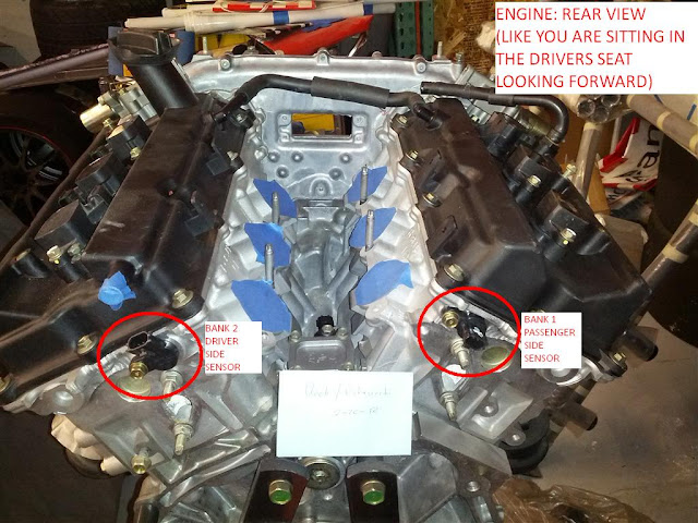
Edit #3 April 25, 2012: Many members have contributed photos and tips making this thread more informative and easy to follow. Below is a picture of the back of the motor, with the bank 1 and 2 sensors clearly identified. Remember, this picture is showing just as the motor would appear if you were sitting in the drivers seat of your car looking forward over the hood. Also, it appears most people are having trouble getting the connector off of the sensor. I am telling you from experience the way I have outlined works. However, other members have suggested pushing on the sensor from the base and the green tab may unlatch itself. Also, another suggestion was to use a long needle nose plier to press down on the green tab and then pull up on the plug at the same time. Bottom line, the green tab must be depressed before the connector will unlatch from the sensor. How you get this done doesn't matter, just know the connector will not come off until the green tab is depressed. One other thing I will point out is that many members have gone with aftermarket sensors from Autozone, Orilley's, etc. and have reported no ill side effects. Although personally I think I would stick with OEM Infinity/Nissan parts, it seems like many people have had good luck with the regular parts store stuff as well. Lastly, if you have something I can add here in the beginning that will make this thread better, shoot me a PM and I will add your info and edit this accordingly. Thanks.
Hope this was helpful. For search purposes, following codes may be related to this thread/repair: P0011 INT/V TIM CONT-B1, P0021 INT/V TIM CONT-B2, P1111 INT/V TIM V/CIR-B1, P1136 INT/V TIM V/CIR-B2, P0340 CMP SEN/CIRC-B1, P0345 CMP SEN/CIRC-B2, P0335 CKP SEN/CIRCUIT
Bank 2 sensor Driver side:
1) Remove the air intake tube from the air filter housing all the way up to the throttle body.
2) Remove the the throttle body electrical connector.
3) Remove the throttle body (in blue). It's held in place by 4 hex bolts. Remove all 4 bolts and the throttle body will come right off. Just below it (in green) is the cam sensor. PHOTO #1
4) Remove the PCV hose (Large black hose which connects from the manifold to the air intake tube).
5) Unclip connector from sensor. (see photo) PHOTO #2
NOTE: It was brought to my attention the sensor my not come off by simply pressing down on the green tab. If you run into this problem, try pushing on the sensor from the base and the tab may unlatch itself.
NOTE 2: If all else fails, remove the 10mm bolt, and pull the sensor out with the clip still attached to the sensor. After the sensor and clip are removed, you should have more room to unlatch the clip
^^^Photo provided courtesy of CLRH2O
6) Remove 10mm bolt from sensor and pull. The sensor may be difficult to remove from it's orifice. The O-ring that seals it my be making it difficult to remove. Just keep pulling and it will come out. PHOTO #3
7) After the sensor is removed test it. See the diagram below to do this. PHOTO #4
Re-installation: Install all parts in reverse order as above.
Bank 1 sensor Passenger side:
This sensor can be removed without removing any parts.
1) Unclip connector from sensor. (see photo) PHOTO #2
2) Reach back with a 3/8" drive socket wrench with a 3" extension and a standard (as opposed to deep) 10mm socket. Unbolt the sensor and replace.
PHOTO #5 This photo and instruction was provided by: mark95tt https://g35driver.com/forums/members...-mark95tt.html
3) This sensor is tested the same way as the driver side sensor. See diagram below for testing instructions. PHOTO #4
4)Replace sensor in reverse order of removal.
Edit #1 April 25, 2012: Ok, so now you replaced your sensor(s) but your service engine soon light ( SES ) is still on. How do I get my light to turn off???
Basic ECU Reset
Procedure:
1. Confirm that accelerator pedal is fully released, turn ignition switch “ON” (NOT start) and wait 3 seconds.
2. Repeat the following steps (2a and 2b) procedures quickly five times within 5 seconds.
2a. Fully depress the accelerator pedal (HARD).
2b. Fully release the accelerator pedal.
3. Wait 7 seconds, fully depress the accelerator pedal and keep it for approx. 10 seconds until the CEL starts blinking.
4. Fully release the accelerator pedal (while the CEL is still blinking)
5. Wait about 10 seconds.
6. Fully depress the accelerator pedal and keep it for more than 10 seconds.
7. Fully release the accelerator pedal (The CEL light will continue to blink).
8. Turn ignition switch to “OFF” position and now you can start the car. The CEL light should be gone. If the CEL light continues to remain ON, repeat the above steps. Remember, timing is EXTREMELY critical to resetting the ECU.
Note: After you perform step 3, the CEL will start flashing. The series of flashes will actually display codes if any are present.
Now take the car out for a drive. If the light comes back on in 5 or 10 miles, then your sensor replacement did not fix your problem. This could be due to a variety of things but is not limited to the following:
1.) Your new sensor is bad (many people suggest only using Nissan/Infiniti OEM parts.)
2.) Your connector may be loose.
3.) You replaced the wrong sensor (this only applies if you only changed 1 of the 2 sensors)
4.) Your cam sensor was not the problem in the first place (Hence, you changed out a good sensor without properly troubleshooting it and wasted your time and money.)
If you changed your sensor out and are still experiencing the exact same issues, re-check the engine code you are getting and troubleshoot according to the FSM. Be mindful that the CKP sensor is often linked to cam sensor error codes, and the CKP could also be contributing to your issues. Do all the testing possible, and then replace parts. Just because you are getting a cam sensor engine code, does not necessarily always mean the cam sensor is bad.
Edit #2 April 25, 2012: I have been asked many times how to properly test the sensor. The following should answer most questions involving this:
No matter what terminals you are testing, you are simply looking for any resistance reading. The resistance will vary according to many factors (temperature, connection quality, sensor wear, your meter etc.). All this test is really meant to check for is an open circuit within the sensor. If the sensor is reading open while you are correctly performing the test, then it is definitely bad. If your meter is reading anything but open, then your sensor is technically passing this test. This doesn't necessarily mean the sensor is positively good though. A very high resistance reading would also likely indicate a problem, but will not show as open on your meter. Since there is no resistance specification listed to determine if you sensor is good or bad, just look for an open when testing. If you are getting funny readings while correctly testing and are in doubt, I would just replace it depending on what codes and symptoms you are experiencing. The key to this is CORRECTLY testing. If you perform the test incorrectly, you will get false readings and may end up purchasing a new sensor thinking it's bad, when in fact, yours was good all along. Make sure you get the polarity right when you are testing the terminals, and also make sure the positive tester lead goes on the correct terminal and vise versa.
Test 1.)
Positive meter (red lead) lead goes on terminal #1. Place the negative lead (black lead) on terminal 2. Your meter should read a resistance value NOT open.
Test 2.)
Positive meter (red lead) lead goes on terminal #1. Place the negative lead (black lead) on terminal 3. Your meter should read a resistance value NOT open.
Test 3.)
Positive meter (red lead) lead goes on terminal #2. Place the negative lead (black lead) on terminal #3. Your meter should read a resistance value NOT open.
Like I said above, you are simply looking for a closed circuit, not a specific resistance reading. See the diagram below for the terminal numbers and more testing information.
Edit #3 April 25, 2012: Many members have contributed photos and tips making this thread more informative and easy to follow. Below is a picture of the back of the motor, with the bank 1 and 2 sensors clearly identified. Remember, this picture is showing just as the motor would appear if you were sitting in the drivers seat of your car looking forward over the hood. Also, it appears most people are having trouble getting the connector off of the sensor. I am telling you from experience the way I have outlined works. However, other members have suggested pushing on the sensor from the base and the green tab may unlatch itself. Also, another suggestion was to use a long needle nose plier to press down on the green tab and then pull up on the plug at the same time. Bottom line, the green tab must be depressed before the connector will unlatch from the sensor. How you get this done doesn't matter, just know the connector will not come off until the green tab is depressed. One other thing I will point out is that many members have gone with aftermarket sensors from Autozone, Orilley's, etc. and have reported no ill side effects. Although personally I think I would stick with OEM Infinity/Nissan parts, it seems like many people have had good luck with the regular parts store stuff as well. Lastly, if you have something I can add here in the beginning that will make this thread better, shoot me a PM and I will add your info and edit this accordingly. Thanks.
Hope this was helpful. For search purposes, following codes may be related to this thread/repair: P0011 INT/V TIM CONT-B1, P0021 INT/V TIM CONT-B2, P1111 INT/V TIM V/CIR-B1, P1136 INT/V TIM V/CIR-B2, P0340 CMP SEN/CIRC-B1, P0345 CMP SEN/CIRC-B2, P0335 CKP SEN/CIRCUIT
Last edited by Silver tiburon; 01-27-2016 at 09:35 PM. Reason: Updates
The following 62 users liked this post by Silver tiburon:
03Sedan6MT (11-14-2015),
2legit2quit (10-09-2014),
abailey362 (01-17-2013),
abrecos (06-18-2017),
Alexus-Kia (06-07-2014),
and 57 others liked this post.
#2
03-15-2011, 02:21 AM
The following 8 users liked this post by Silver tiburon:
2legit2quit (10-09-2014),
Famous Amos (07-02-2018),
Fresh&SoClean (08-25-2023),
G35Papa (03-28-2012),
geo723 (10-09-2014),
and 3 others liked this post.
#3
03-15-2011, 03:24 AM

Registered User
#4
03-24-2011, 01:39 PM
Crankshaft Position Sensor
Another note:
The crankshaft position sensor looks almost identical to the cam sensor and is tested the same way as seen in photo #4.
Edit #4 May 24, 2012:
So it seems like lots of people are relying to Autozone, Orilley's, Advance and other parts store chains to read their trouble codes because they don't know how to do it themselves. Reading the codes your ECU is throwing is easy, fast and can be done anywhere with no tools. All you need is your car keys, a brain and usually something to write dots and dashes on. I will outline the procedure to do this below. All credit for this can be attributed to another forum user on nicoclub.com: http://forums.nicoclub.com/how-to-re...s-t488116.html
The following tutorial will tell you how to read the DTC’s (Diagnotic Trouble Codes) from your vehicles ECM (engine control module) for free in only a matter of minutes. When you start and drive your vehicle normally, the vehicles ECM is operating in what is called Diagnostic Test Mode I, it is constantly polling the various sensors and actuators to make sure everything is operating as it should. Once the ECM detects a problem with the vehicle, it will store a specific DTC that corresponds to that specific problem. After the ECM detects the problem for the first time, the SERVICE ENGINE SOON lamp will not illuminate (unless the DTC is for a misfire, three way catalyst function or closed loop control). However, if that same problem occurs the next time you drive the vehicle, the ECM will then illuminate the SERVICE ENGINE SOON lamp to let you know that there is a problem with your vehicle.
To figure out what is wrong with your vehicle you must first extract the DTC from the ECM so that you can begin troubleshooting the problem. Generally this task is done with an OBD-II reader which you plug into the OBD-II plug under the driver knee trim. If you were to take the vehicle to the dealership to extract the DTC they would hook your vehicle up to the CONSULT computer which would immediately tell them the DTC. The third method, which is explained below, is a DIY method which requires no tools and no expensive computers and can be done in your driveway.
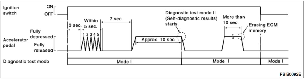
1. Confirm that accelerator pedal is fully released, turn ignition switch “ON” (not starting vehicle) and wait 3 seconds.
2. Repeat the following procedure quickly five times within 5 seconds:
a) Fully depress the accelerator pedal.
b) Fully release the accelerator pedal.
3. Count to 10 seconds, fully depress the accelerator pedal and keep it for approximately 10 seconds until the SERVICE ENGINE SOON lamp starts blinking.
4. Fully release the accelerator pedal.
The ECM has entered to Diagnostic Test Mode II (Self-diagnostic results).
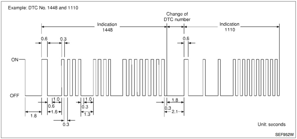
Once the ECM has entered Diagnostic Test Mode II, it will immediately begin displaying the DTC’s via SERVICE ENGINE SOON lamp blinks. A particular trouble code can be identified by the number of four-digit numeral flashes. The “zero” is indicated by the number of ten flashes. The length of time the 1,000th-digit numeral flashes on and off is 1.2 seconds consisting of an ON (0.6-second) - OFF (0.6-second) cycle. The 100th-digit numeral and lower digit numerals consist of a 0.3-second ON and 0.3-second OFF cycle.
A change from one digit numeral to another occurs at an interval of 1.0-second OFF. In other words, the later numeral appears on the display 1.3 seconds after the former numeral has disappeared. A change from one trouble code to another occurs at an interval of 1.8-second OFF. In this way, all the detected malfunctions are classified by their DTC numbers. The DTC “0000” refers to no malfunction.
Below is an example of an ECM with two DTC’s stored, 1448 and 1110, respectively. Note the duration and separation of each SES blink.
The crankshaft position sensor looks almost identical to the cam sensor and is tested the same way as seen in photo #4.
Edit #4 May 24, 2012:
So it seems like lots of people are relying to Autozone, Orilley's, Advance and other parts store chains to read their trouble codes because they don't know how to do it themselves. Reading the codes your ECU is throwing is easy, fast and can be done anywhere with no tools. All you need is your car keys, a brain and usually something to write dots and dashes on. I will outline the procedure to do this below. All credit for this can be attributed to another forum user on nicoclub.com: http://forums.nicoclub.com/how-to-re...s-t488116.html
The following tutorial will tell you how to read the DTC’s (Diagnotic Trouble Codes) from your vehicles ECM (engine control module) for free in only a matter of minutes. When you start and drive your vehicle normally, the vehicles ECM is operating in what is called Diagnostic Test Mode I, it is constantly polling the various sensors and actuators to make sure everything is operating as it should. Once the ECM detects a problem with the vehicle, it will store a specific DTC that corresponds to that specific problem. After the ECM detects the problem for the first time, the SERVICE ENGINE SOON lamp will not illuminate (unless the DTC is for a misfire, three way catalyst function or closed loop control). However, if that same problem occurs the next time you drive the vehicle, the ECM will then illuminate the SERVICE ENGINE SOON lamp to let you know that there is a problem with your vehicle.
To figure out what is wrong with your vehicle you must first extract the DTC from the ECM so that you can begin troubleshooting the problem. Generally this task is done with an OBD-II reader which you plug into the OBD-II plug under the driver knee trim. If you were to take the vehicle to the dealership to extract the DTC they would hook your vehicle up to the CONSULT computer which would immediately tell them the DTC. The third method, which is explained below, is a DIY method which requires no tools and no expensive computers and can be done in your driveway.
1. Confirm that accelerator pedal is fully released, turn ignition switch “ON” (not starting vehicle) and wait 3 seconds.
2. Repeat the following procedure quickly five times within 5 seconds:
a) Fully depress the accelerator pedal.
b) Fully release the accelerator pedal.
3. Count to 10 seconds, fully depress the accelerator pedal and keep it for approximately 10 seconds until the SERVICE ENGINE SOON lamp starts blinking.
4. Fully release the accelerator pedal.
The ECM has entered to Diagnostic Test Mode II (Self-diagnostic results).
Once the ECM has entered Diagnostic Test Mode II, it will immediately begin displaying the DTC’s via SERVICE ENGINE SOON lamp blinks. A particular trouble code can be identified by the number of four-digit numeral flashes. The “zero” is indicated by the number of ten flashes. The length of time the 1,000th-digit numeral flashes on and off is 1.2 seconds consisting of an ON (0.6-second) - OFF (0.6-second) cycle. The 100th-digit numeral and lower digit numerals consist of a 0.3-second ON and 0.3-second OFF cycle.
A change from one digit numeral to another occurs at an interval of 1.0-second OFF. In other words, the later numeral appears on the display 1.3 seconds after the former numeral has disappeared. A change from one trouble code to another occurs at an interval of 1.8-second OFF. In this way, all the detected malfunctions are classified by their DTC numbers. The DTC “0000” refers to no malfunction.
Below is an example of an ECM with two DTC’s stored, 1448 and 1110, respectively. Note the duration and separation of each SES blink.
Last edited by Silver tiburon; 05-24-2012 at 01:39 AM. Reason: Updates
#5
05-05-2011, 04:44 PM
The following 4 users liked this post by TwoFiveBravo:
#6
05-06-2011, 03:02 PM

Registered User
Join Date: Jan 2011
Location: Atlanta, GA
Posts: 55
Likes: 0
Received 0 Likes
on
0 Posts
#7
05-06-2011, 03:09 PM
Trending Topics
#8
05-06-2011, 03:12 PM
Registered User
Join Date: Jan 2011
Location: Atlanta, GA
Posts: 55
Likes: 0
Received 0 Likes
on
0 Posts
How much are they from the dealer? Advance is charging me $54
#9
05-06-2011, 03:39 PM
#10
05-12-2011, 11:09 PM

#11
05-12-2011, 11:20 PM
 pass side sensor is straight and drivers side is bent. I would suggest buying it from Nissan. Like I said I bought one from a parts store for $60 and it lasted about 2 days.
The following 2 users liked this post by TwoFiveBravo:
Hanoon (08-05-2015),
PongSanity (01-15-2013)
#14
05-13-2011, 08:59 PM
The following users liked this post:
Chadonne Knight (10-17-2020)
#15
05-13-2011, 11:38 PM

The following users liked this post:
Chadonne Knight (10-17-2020)

